What is a CDI System? A Capacitor
Discharge Ignition is an electronic ignition device that stores an
electrical charge and then discharges it through an ignition coil in
order to produce a powerful spark from the spark plugs in a petrol
engine. Here the ignition is provided by the capacitor charge. The
capacitor simply charges and discharges within a fraction of time making
it possible to create sparks CDIs are commonly found on motorbikes and
scooters.
Working principle a CDI System
A capacitor discharge ignition works by
passing an electrical current over a capacitor. This type of ignition
builds up a charge quickly. A CDI ignition starts by generating a charge
and storing it up before sending it out to the spark plug in order to
ignite the engine.
This power passes through a capacitor and is transferred to an ignition coil that helps boost the power by acting as a transformer and allowing the energy pass through it instead of catching any of it.
The CDI ignition systems, therefore,
allow the engine to keep running as long as there is a charge in the
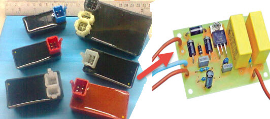
power source. The block diagram of CDI shown below.

Working of Capacitor Discharge Ignition
A Capacitor Discharge Ignition consists
of several parts and is integrated with the ignition system of a
vehicle. The foremost parts of a CDI include the stator, charging coil,
hall sensor, flywheel and the timing mark.
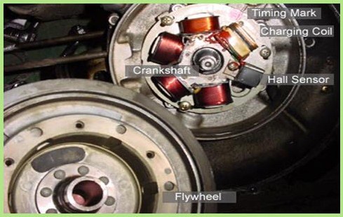
Flywheel and Stator
The flywheel is a large horseshoe
permanent magnet rolled into a circle that turns-ON the crankshaft. The
Stator is the plate holding all of the electrical coils of wire, which
is used to power ON the ignition coil, bike’s lights, and battery
charging circuits.
Charging Coil
The charging coil is one coil in the
stator, which is used to produce 6 volts to charge the capacitor C1.
Based on the flywheel’s movement the single pulsed power is produced and
it supplied to the sparking plug by the charging coil to ensure the
maximum spark.
Hall Sensor
The Hall Sensor measures the hall
effect, the instantaneous point where the flywheel’s magnet changes from
a north to a south pole. When the pole change occurs, the device sends a
single, tiny pulse to the CDI box which triggers it to dump the energy
from the charging capacitor into the high voltage transformer.
Timing Mark
The timing mark is an arbitrary
alignment point shared by the engine case and stator plate. It indicates
the point at which the top of the piston’s travel is equivalent to the
trigger point on the flywheel and stator.
By rotating the stator plate left and
right, you effectively change the trigger point of the CDI, thus
advancing or retarding your timing, respectively. As the flywheel turns
fast, the charge coil produces an AC current from +6V to -6V.
The CDI box has a collection of
semiconductor rectifier that connected to G1 on the box allows only the
positive pulse to enter the capacitor (C1). While the wave entering into
the CDI, the rectifier allows only the positive wave.
Trigger Circuit
The trigger circuit is a switch, probably using a Transistor, Thyristor or SCR.
This triggered by a pulse from the Hall Sensor on the stator. They only
allow current from one side of the circuit until they are triggered.
Once the Capacitor C1 is fully charged,
the circuit can be triggered again. This is why there is timing involved
with the motor. If the capacitor and stator coil were perfect, they
would charge instantaneously and we can trigger them as fast as our
wish. However, they require a fraction of a second to full charge.
If the circuit triggers too fast, then
the spark from the spark plug will be enormously weak. Certainly, with
the higher accelerating motors, we may have the triggering faster than
the capacitor full charge, which will affect performance. Whenever the
capacitor is discharged, then the switch turns itself off and the
capacitor charges again.
The trigger pulse from the Hall sensor
feeds into the gate latch and allows all the stored charge to rush
through the primary side of the high-voltage transformer. The
transformer has a common ground between the primary and secondary
windings, known as an auto step-up transformer.
Therefore, as if we increase the
windings on the secondary side, you will multiply the voltage. Since a
spark plug needs a good 30,000 volts to sparks, there must be many
thousands of wraps of wire around the high voltage or secondary side.
When the gate opens and dumps all the
current into the primary side, it saturates the low-voltage side of the
transformer and sets up a short but immensely magnetic field. As the
field reduces gradually, a large current in the primary windings force
the secondary windings to produce extremely high voltage.
However, the voltage is now so high that
it can arc through the air, so rather than being absorbed or retained
by the transformer, the charge travels up the plug wire and jumps the
plug gap.
When we want to shut down the motor
engine, we have two switches the key switch or the kill switch. The
switches ground out the charging circuit so the entire charging pulse is
sent to ground. Since the CDI can no longer charge, it will cease to
provide the spark and the engine will slow to a stop.
Advantages of CDI
- The major advantage of CDI is that the capacitor can be fully charged in a very short time (typically 1ms). So the CDI is suited to application where the insufficient dwell time is available.
- The capacitor discharge ignition system has a short transient response, a fast voltage rise (between 3 to 10 kV/ µs) compared to inductive systems (300 to 500 V/ µs) and shorter spark duration (about 50-80 µs).
- The fast voltage rising makes CDI systems unaffected to shunt resistance.
Disadvantages of CDI
- The capacitor discharge ignition system generates huge electromagnetic noise and this is the main reason why CDIs are rarely used by automobile manufacturers.
- The short spark duration is not good for lighting relatively lean mixtures as used at low power level. To solve this problem many CDI ignitions release multiple sparks at low engine speeds.


No comments:
Post a Comment