Voltage Divider, in fact is a fundamental circuit in the field of electronics which can produce a portion of its input voltage as output. It is formed using two resistors or any passive components and a voltage source.
The resistors are connected in series here and the voltage is given
across these two resistors. This circuit is also termed as potential divider.
The input voltage is distributed among the resistors (components) of
the voltage divider circuit. As a result, voltage division takes place.
 In the above figure, (A) represents shorthand, (B) represents longhand
and (C) and (D) shows the resistors in different and same angle
respectively.
But all the four circuits are in effect the same. R1 is the resistor which is always close to the input voltage source and R2 is the resistor which is near to the ground. Vout is the voltage drop across the resistor, R2. It is actually the divider voltage which we get from this circuit as the output.
In the above figure, (A) represents shorthand, (B) represents longhand
and (C) and (D) shows the resistors in different and same angle
respectively.
But all the four circuits are in effect the same. R1 is the resistor which is always close to the input voltage source and R2 is the resistor which is near to the ground. Vout is the voltage drop across the resistor, R2. It is actually the divider voltage which we get from this circuit as the output.
 Under open circuit output condition; that is there will be no current flow in the output side, then
 Now we can prove the output voltage equation (1) using the basic law, Ohm’s Law
  .
.
 Substitute equation (4) in (3), we get
 So, the equation is proved.
The transfer function of the above equation is This equation is also called as Divider’s
 The capacitive divider circuits never allow DC input to pass. They work on AC input.
For Inductive divider with non-interacting inductors, the equation becomes The inductive divider divides the DC input analogous to resistor divider circuit depending on resistance and it divides AC input with regard to the inductance.
A basic Low-pass RC filter circuit is shown below which comprises of a resistor and capacitor.
 C → Capacitance
R → Resistance
XC → Reactance of the capacitor
ω → Radiant frequency
j → Imaginary unit
Here, the divider’s voltage ratio is RC → Time constant of the circuit represented as τ.
 R2 and RL are parallel to each other.
 The circuit with loaded condition is shown below.

Circuit of Voltage Divider
As we mentioned above, two series resistors and voltage source constitutes a simple voltage divider. This circuit can be formed in several ways as shown below.
In the above figure, (A) represents shorthand, (B) represents longhand
and (C) and (D) shows the resistors in different and same angle
respectively.
But all the four circuits are in effect the same. R1 is the resistor which is always close to the input voltage source and R2 is the resistor which is near to the ground. Vout is the voltage drop across the resistor, R2. It is actually the divider voltage which we get from this circuit as the output.
Equation of Voltage Divider in Unloaded Condition
The simple voltage divider circuit with reference to ground is shown in the figure below. Here, two electrical impedances (Z1 and Z2) or any passive components are connected in series. The impedances may be of resistors or inductors or capacitors. The output of the circuit is taken across the impedance, Z2.
Under open circuit output condition; that is there will be no current flow in the output side, then
Now we can prove the output voltage equation (1) using the basic law, Ohm’s Law .
Substitute equation (4) in (3), we get
So, the equation is proved.The transfer function of the above equation is
This equation is also called as Divider’s
The capacitive divider circuits never allow DC input to pass. They work on AC input.For Inductive divider with non-interacting inductors, the equation becomes
The inductive divider divides the DC input analogous to resistor divider circuit depending on resistance and it divides AC input with regard to the inductance.A basic Low-pass RC filter circuit is shown below which comprises of a resistor and capacitor.
C → Capacitance R → Resistance
XC → Reactance of the capacitor
ω → Radiant frequency
j → Imaginary unit
Here, the divider’s voltage ratio is
RC → Time constant of the circuit represented as τ.
Voltage Divider Under Loaded Condition
Now, we can see the voltage divider circuit in loaded condition. Here, the resistors (R1 and R2) are taken for simplicity. A resistor (RL) is connected across the output. Then the equation becomes,
R2 and RL are parallel to each other.
The circuit with loaded condition is shown below.
 V → Voltage Drop (V)
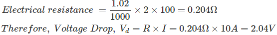
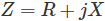 The amount of Z depends on the factors such as magnetic permeability, electrical isolating elements and the frequency of AC.
 E → Voltage Drop (V)
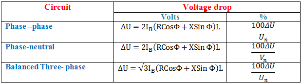 IB → Full load current (A)
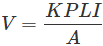 L → Wire length (ft)
 f is the factor we get from the standard table below.


